
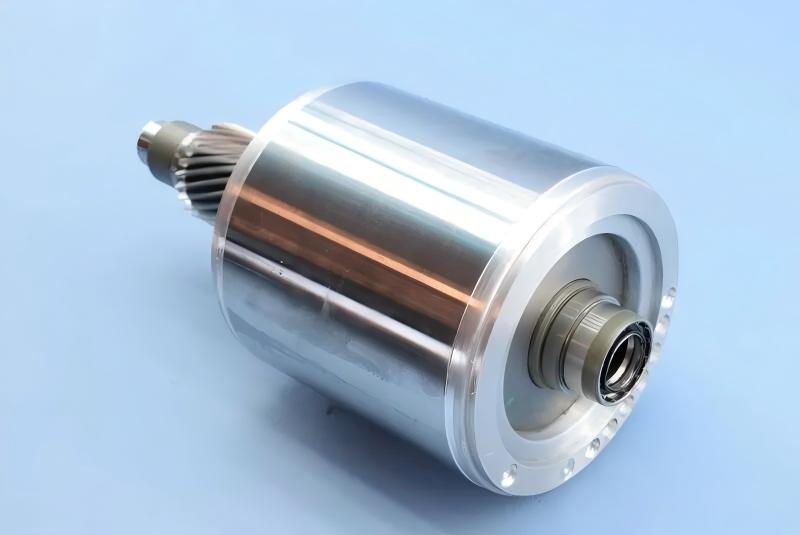
Almost every three-phase induction motor built today carries a cast aluminum rotor. The cast cage, end rings, cooling fins, and balance bosses are formed as one piece around the laminated core, giving the rotor low inertia, high torque-to-weight ratio, and a low manufacturing cost that copper bar rotors cannot match. For EV traction motors, that combination has made the cast aluminum rotor the default choice.
But casting aluminum around a stacked steel core is not simple. Air entrapment, shrinkage porosity, and broken bars ruin rotors silently, and the defects often pass visual inspection. This article covers the five casting methods and why only two dominate production, the material and process parameters that experienced foundries control, the quality checks that matter, and what an automated rotor die-casting island must do to hold those parameters at volume.
Five casting methods, and why two survive
Rotor aluminum casting has five recognized methods: vibration casting, gravity casting, centrifugal casting, pressure (die) casting, and low-pressure casting.
Vibration casting and gravity casting give poor feeding to the lower end ring during solidification, so shrinkage porosity is common and both are rarely used. Low-pressure casting produces excellent rotors but has not been widely adopted by mainstream motor manufacturers.
Two methods carry the industry.
1. Pressure die casting. Molten aluminum is injected into the mold cavity under high pressure and solidifies under that pressure. Pressure dominates the entire cycle. The rotor core can be cast in a cold state, cycle time is short, and the process lends itself to full mechanization and automation. The weakness is air entrapment: metal fills the cavity at high speed, and if mold venting is insufficient, gas folds into the casting as porosity.
2. Centrifugal casting. Molten aluminum is poured into a rotating mold, and centrifugal force fills the cavity and drives solidification. The force helps expel gas and non-metallic inclusions (lighter than the metal), strengthens feeding, and refines the grain structure. The equipment is simpler than a die-casting machine, but pouring involves significant manual work, and labor intensity is high.
For volume rotor production, pressure die casting wins on cycle time and automation capability. That is why modern rotor die-casting islands are built around the cold-chamber die-casting machine.
Pressure die casting: machine, mold, and parameters
Rotor pressure die casting uses a cold-chamber machine, in fully vertical, vertical, or horizontal configurations. Key machine ratings are injection force, injection speed, clamping force, injection specific pressure, and maximum aluminum shot weight. The injection system is the quality-critical component: production machines today mostly use three-stage injection.
The die-casting mold treats the laminated rotor core as an insert, and the core slots form part of the cavity. Gate design matters: horizontal and vertical machines typically use center gating through runners to several inner gates placed at the thick end ring for good feeding; fully vertical machines often use fin-face gating. Because cavity fill time is extremely short, the mold must carry generous venting so air escapes in an orderly way.
Because molten aluminum flows poorly and the casting walls are thick, the specific pressure should be high while the fill speed stays deliberately low. Typical parameters for small motor rotors: injection specific pressure 29.4 to 39.2 MPa, fill speed 15 to 25 m/s, pouring temperature 680 to 700 degrees C, mold temperature 180 to 200 degrees C. These parameters interact and are tuned by trial molding; with fin-face gating, pressure losses are lower and specific pressure can be slightly reduced.
For centrifugal casting, aluminum temperature is held higher at 720 to 780 degrees C, mold temperature at 450 to 550 degrees C, and the centrifuge speed is set from the end ring geometry. A variable-speed centrifuge is preferred over constant-speed.
Material requirements: purity is a conductivity problem
Rotor casting uses grade one remelted aluminum ingot, A1 99.5 or A1 99.7 per GB 1196, with resistivity at 20 degrees C of 0.027 to 0.03 ohm square millimeter per meter and purity not below 99.5 percent. Impurity limits for A1 99.5: iron 0.3 percent, silicon 0.25 percent, iron plus silicon 0.45 percent, copper 0.015 percent, total impurities 0.5 percent.
After melting, the molten aluminum may exceed the ingot iron limit but must stay below 0.8 percent iron and 1 percent total impurities, while resistivity must still meet the ingot specification. Every shift, the crucible melt is sampled and analyzed before production.
Melting practice matters as much as composition. A cast iron crucible must be coated with a protective high-temperature coating before use to prevent iron pickup into the melt. Gate and runner returns must stay below 15 percent of the charge to protect melt purity. Degassing and slag removal are done with chloride salts such as sodium chloride at 0.1 to 0.5 percent of the melt weight, to exhaust gas and remove inclusions.
Pre-casting checks on the laminated core are equally strict: burrs within drawing limits, no oil or rust on laminations, teeth smooth and flat. Scrapped rotors may be remelted once; laminations that have been remelted twice must not be reused.
Quality control: the checks that decide rotor life
1. Core length tolerance: plus 2.0 mm for cores under 160 mm, plus 2.5 mm for longer cores. 2. Skew line on the rotor outer diameter must be straight, without visible bends, and skew dimensions must meet the drawing. 3. Burrs and flash on end rings and fins, and residual aluminum on the core outer diameter, must be cleaned completely. No aluminum may be trapped between laminations or inside the shaft bore. 4. End ring shrinkage porosity: at most three spots, each under 3 mm deep and under 5 mm in diameter. End rings and fins must be free of cracks, bending, inclusions, and impact damage; cold shuts on fins may not exceed one quarter of fin length, and missing fin profile may not exceed 3 mm. 5. Balance bosses must be crack-free; missing material may not exceed one fifth of boss height, and at most one quarter of the bosses per end may be affected. 6. Concentricity between the end ring outer diameter and the core outer diameter must meet the specified tolerance grade. 7. Broken or thinned bars are not permitted. Every rotor is tested 100 percent, typically by the current swing comparison method, and the computed swing must not exceed 3 percent. 8. Insufficient fill or depression at slot openings must stay within the specified limits. 9. Scoring depth on the rotor outer diameter may not exceed the finish turning allowance.
Two of these checks deserve emphasis. Broken bar testing is electrical, not visual: a rotor can look perfect and still carry a cracked bar. And the 3 percent current swing limit is the industry gate that separates a shippable rotor from scrap.
What a modern rotor die-casting island must automate
The parameters above are achievable by hand for a few rotors per hour. At production volume, they require a machine cell that holds them consistently:
1. Consistent melt handling. A holding furnace keeps aluminum at temperature, and a soup feeder (auto ladle) meters each shot to the die-casting machine. Shot weight consistency is the first defense against porosity and short fill. 2. Mold temperature control. The mold must sit at 180 to 200 degrees C every cycle. Die-casting islands integrate mold temperature controllers and preheat logic so the first shots of a shift are not scrap. 3. Core handling. Laminated cores arrive as inserts. The cell must load cores, verify skew and orientation, and unload finished rotors without bending fins or scratching the outer diameter. 4. Trimming and separation. The runner and gates are removed in the cell, with trim force controlled so fins and balance bosses are not damaged. 5. 100 percent inspection. Broken bar testing and dimensional checks are integrated as stations in the line, not as sampling at a lab bench. Data per rotor is recorded: shot parameters, mold temperature, and test result.
A cell that cannot hold these five is a press with helpers, not a die-casting island.
Questions to answer before specifying a die-casting island
1. Rotor diameter, core length, and stack height range, and how many rotor models share the line? 2. Aluminum grade and melt specification, and is the melt supplied from one holding furnace or several? 3. Casting method: pressure die casting, centrifugal, or both for different rotor families? 4. Target cycle time and output per shift, and the acceptable scrap rate? 5. Which checks must be recorded per rotor: shot parameters, mold temperature, broken bar test, dimensions? 6. Downstream operations in the same cell: trimming, shaft pressing, turning, balancing?
Frequently asked questions
Q: Why is pressure die casting preferred over centrifugal casting for rotors? A: Cycle time and automation. Pressure die casting fills in milliseconds and integrates cleanly with auto ladles, extraction robots, and trim presses. Centrifugal casting produces good metallurgy but relies on manual pouring, which limits throughput and consistency.
Q: Why does iron content matter in rotor aluminum? A: Iron raises resistivity and hurts motor efficiency. The ingot limit is 0.3 percent, the melt limit 0.8 percent, and the resistivity specification is the binding constraint. Crucible protection coating exists largely to prevent iron pickup.
Q: What is the three-stage injection system on a die-casting machine? A: A shot profile with slow approach, fast fill, and intensification phases. For rotors, the fast fill stage dominates porosity risk because air must escape through the vents before the metal arrives.
Q: How are broken bars detected? A: By the current swing comparison method, an electrical test applied to every rotor. A swing above 3 percent indicates a broken or thinned bar and the rotor is rejected, even if it looks perfect.
Q: What mold temperature should a rotor die cast use? A: Typically 180 to 200 degrees C. Too cold and fill is incomplete; too hot and cycle time and shrinkage porosity suffer. This is why die-casting islands include mold temperature control.
Q: Can a scrapped rotor be remelted? A: Once, yes. Laminations that have been through remelting twice must not be reused, because burr condition and tooth geometry degrade.
Planning a rotor die-casting line or upgrading an existing one? We design turnkey rotor die-casting islands: melting and holding, soup feeder (auto ladle) dosing, die-casting machine, mold temperature control, extraction robot, trimming, and 100 percent inspection stations. Tell us your rotor range, target cycle time, and scrap tolerance, and we will propose an island configuration.
Related capability: rotor die-casting island at https://www.ldmotortech.com/en/products/die-casting Related capability: motor assembly line at https://www.ldmotortech.com/en/products/motor-assembly