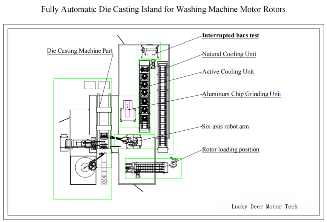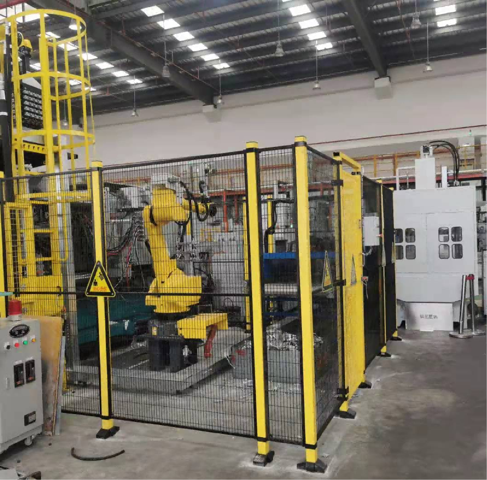
Ask two motor factories what a rotor die casting machine is and you will get two answers. One describes a press. The other describes a cell: a core loading station, a six-axis robot, a die casting machine with an automatic ladle, a grinding station, a cooling unit, and a broken-bar inspection unit working as one line.
The second answer is the one that matters. A motor rotor die-casting island is a complete automated cell in which the rotor core is loaded, cast, extracted, finished, cooled, inspected, and traced in a single continuous flow. It is also the step where the squirrel cage of an induction motor is formed — and the step where hidden defects are either prevented or created. Most buyers start by comparing press tonnage. In practice, throughput and casting quality are decided by how well the stations around the press are balanced with each other.
Why rotor casting is built as a cell, not a single machine
Rotors are cast inside a laminated core that has been stacked and skewed. The molten aluminum has to fill every slot, both end rings, and often cast fan blades in one to three seconds. That leaves very little margin. Four variables have to stay steady at the same time: melt temperature and gas content in the furnace, injection speed and pressure profile, die temperature, and venting or vacuum.
A human operator cannot hold four variables steady across three shifts. An island can, because each station is a fixed, repeatable mechanical action: the robot loads the core the same way every cycle, the sprayer applies the same amount of release agent, the cooling unit takes the rotor to the same temperature before inspection. Stability, not headcount, is the reason these cells exist.
Station by station through a rotor die-casting island
1. Core loading. Stacked and skewed rotor cores are presented to the cell on a loading slide or magazine. The station orients each core and confirms it is present and correctly positioned before the robot picks it, which prevents the most common cause of die damage: a core seated out of position.
2. Pick and place. A six-axis robotic arm with dedicated fixtures handles loading into the mold and unloading after casting. The robot also transfers the rotor between the downstream stations, which is what turns a group of machines into one continuous flow instead of a series of manual handoffs.
3. The die casting machine and the automatic ladle. The press closes on the core and molten aluminum is dosed into the shot sleeve. The dosing device is an automatic ladle, known in some markets as a soup feeder, which transfers a measured volume from the holding furnace on every cycle. Consistent dosing volume is what keeps fill behaviour and end ring formation repeatable.
4. Die temperature control, servo sprayer, and release agent dosing. Between shots the die is sprayed and its temperature is held in a narrow band, typically monitored by the cell controller. Undercooled dies cause cold shuts and misruns; overheated dies cause sticking and longer cycles. A servo sprayer applies release agent in a controlled pattern instead of flooding the cavity.
5. Grinding and polishing. After the rotor is removed from the mold, the robot places it on a grinding and polishing station for surface treatment. This removes the gate mark and flash and brings the casting to the condition the downstream machining and balancing operations expect.
6. Controlled air cooling. Casting inspection results are temperature dependent, so rotors are taken to a defined temperature in an air-cooled unit before testing. Cooling to a stable temperature is what makes the electrical inspection that follows meaningful rather than approximate.
7. Broken-bar inspection. This station checks the cooled rotor for broken or incompletely formed cage bars. A broken bar raises rotor resistance, increases losses, and reduces torque — and it cannot be seen from outside. Inline broken-bar inspection is the last gate before a rotor is accepted, and it is the single most valuable check in the cell.
8. Traceability. Modern islands log shot parameters, die temperature, and inspection results against a rotor serial number. When a motor fails a performance test later, that record is what lets a factory trace back to the shift, the die, and the melt batch that produced the rotor.
What sets the cycle time and hourly output
The cell cycle is not the casting cycle. It is the longest station time in the sequence plus the robot handling time between stations. A press that fills and solidifies in 20 seconds can still be held to 45 seconds by spray and dosing, or to 60 seconds by cooling.
The useful calculation is simple. Take the cell cycle in seconds, divide 3600 by it to get theoretical pieces per hour, then apply an availability factor for die changes, spray adjustments, and planned stops. A 45-second cell cycle gives 80 rotors per hour theoretical; at 85 percent availability that is roughly 68 rotors per hour. Ask any supplier which number their proposal is based on, because the gap between theoretical and real output is where schedules are missed.
What to define before you request a quote
1. Rotor range. Core diameter, stack length, slot geometry, skew angle, and whether fan blades or balance features are cast in one shot. 2. Alloy and process level. Standard aluminum casting, or vacuum-assisted casting for high-efficiency and EV rotors with tight porosity limits. 3. Hourly output and shift pattern, including whether the cell must run unattended. 4. Automation level at each station, from manual core loading up to fully automatic loading, transfer, and inspection. 5. Inspection and data requirements: broken-bar testing, weight check, end ring vision inspection, X-ray sampling, and whether results must be logged to a traceability system. 6. Floor space, utilities, and fume extraction available at the installation site.
The clearer this list is, the more accurately a cell can be configured — and the less likely you are to buy capacity you cannot use, or discover a bottleneck after installation.
Frequently asked questions
Q: What is the difference between a die casting machine and a die casting island? A: The machine performs the casting. The island is the complete cell around it: core loading, robotic handling, dosing, spraying, finishing, cooling, inspection, and traceability. Output and consistency come from the cell, not from the press alone.
Q: What is a soup feeder? A: It is the automatic ladle that transfers a measured volume of molten aluminum from the holding furnace into the shot sleeve on every cycle. Consistent dosing volume is essential to repeatable cage formation.
Q: Why is broken-bar inspection needed if the casting looks sound? A: Cage defects are internal. A broken or incompletely filled bar cannot be seen from outside but raises rotor resistance and reduces motor efficiency. Electrical broken-bar testing detects it non-destructively on every rotor.
Q: How much floor space does a rotor die-casting island need? A: It depends on the number of stations and the cooling method. A compact appliance rotor cell fits in a modest bay, while a large industrial rotor cell with extended cooling and full inspection needs considerably more. Your supplier should supply a layout drawing with the proposal.
Q: Can one island handle several rotor models? A: Yes, if the range is defined upfront. Changeover is handled through program recall, fixture change, and die change, so the cell covers a rotor family rather than a single part number.
Planning a rotor die casting project? We build turnkey motor rotor die-casting islands, from core loading and robotic handling through cooling, broken-bar inspection, and traceability. Tell us your rotor range, alloy, and target hourly output, and we will propose a cell configuration.
Related capability: motor rotor die-casting island at https://www.ldmotortech.com/en/products/die-casting Related capability: motor assembly automation at https://www.ldmotortech.com/en/products/motor-assembly